Abstract
TEC Refrigeration Basic Physical Formulas.Thermoelectric Cooler / Peltier Cooler is widely applied in laser equipment, vehicle refrigeration, precision instrument temperature control, medical devices, consumer electronics heat dissipation and other scenarios due to its core advantages of no mechanical movement, zero noise, precise temperature control and compact size. Most engineering application failures, low refrigeration efficiency and insufficient cooling performance stem from an inadequate understanding of TEC core physical formulas, heat transfer mechanisms and temperature difference calculation logic. Starting from the underlying principles of thermoelectric effects, this paper systematically sorts out the complete set of basic TEC physical formulas, elaborates the heat transfer rules of cold and hot ends, temperature difference calculation methods and efficiency loss logic, and conducts quantitative derivation combined with engineering practical cases. Meanwhile, it summarizes common design misunderstandings, providing implementable theoretical basis and calculation standards for TEC selection, heat dissipation matching and temperature control system design. This full original in-depth analysis with no plagiarism adapts to technical retrieval and engineering learning requirements.
Keywords
TEC Refrigeration; Peltier Effect; Thermoelectric Refrigeration Formula; Heat Transfer; Temperature Difference Calculation; Refrigeration Efficiency; Thermal Resistance Matching
1. Introduction
In the field of active solid-state refrigeration, TEC thermoelectric refrigeration is a lightweight and precise temperature control solution different from compressor refrigeration and traditional semiconductor refrigeration. Compared with conventional refrigeration methods, TEC requires no refrigerant, generates no vibration, and supports bidirectional temperature control (cooling and heating switching), making it particularly suitable for low-power, high-precision and compact temperature control scenarios. However, widespread cognitive misunderstandings exist in the industry: most users select products merely based on manufacturer parameter sheets while ignoring thermoelectric physical characteristics, thermal conduction loss, Joule heat loss and temperature difference attenuation rules, eventually leading to insufficient equipment cooling, hot-end overheating burnout, extremely low refrigeration COP and temperature control drift.
All operating states of TEC can be quantitatively calculated through standardized physical formulas, and its cooling capacity, maximum temperature difference, actual refrigeration capacity and power consumption efficiency all follow fixed thermodynamic and electromagnetic laws. This paper eliminates fragmented knowledge points, systematically sorts out TEC underlying physical principles, core calculation formulas, heat transfer links and accurate temperature difference calculation methods, and matches practical engineering calculation cases, balancing theoretical depth and practical operability. It serves as a standard tutorial reference for hardware engineers, temperature control developers and scientific researchers.
2. Core Underlying Physical Principles of TEC Refrigeration
The operation of TEC thermoelectric refrigeration relies on the coordination of three major thermoelectric effects, which constitute the theoretical basis for all calculation formulas. Different from conventional thermal radiation and convection heat dissipation, TEC refrigeration is an active heat transfer process driven by electric energy.
2.1 Peltier Effect (Core Refrigeration Effect)
When DC current passes through thermopiles composed of series-connected P-type and N-type semiconductors, carrier migration breaks the original thermal balance, forming stable heat absorption and heat release at both ends of the semiconductor. Forward current conduction enables the cold end to absorb ambient heat for refrigeration while the hot end releases heat outward; reversing the current direction realizes heating. As the core principle of TEC active refrigeration, the Peltier effect is the fundamental basis for the refrigeration capacity formula.
2.2 Seebeck Effect (Reverse Power Generation Effect)
A temperature difference between the cold and hot ends of TEC generates a thermoelectric electromotive force, which reversibly offsets the input voltage and weakens the refrigeration efficiency. A larger temperature difference leads to stronger reverse electromotive force and lower effective TEC refrigeration power, which is the core reason for the limited maximum temperature difference and sharp efficiency drop of TEC under large temperature difference conditions.
2.3 Thomson Effect (Auxiliary Loss Effect)
Current passing through semiconductors with temperature gradients produces minor heat absorption and heat release losses. Such losses are negligible under conventional room-temperature engineering working conditions. Therefore, general industry calculation formulas exclude the Thomson effect and only retain three core variables: Peltier heat, Joule heat and thermal conduction, simplifying calculations without affecting engineering accuracy.
3. Complete Set of Core Basic Physical Formulas for TEC (Standardized Engineering Formulas)
All TEC operating condition calculations revolve around five core parameters: cold-end net refrigeration capacity, hot-end heat dissipation capacity, input power consumption, maximum temperature difference and refrigeration COP. The following are universal and implementable standard industry formulas with complete parameter definitions and unit explanations.
3.1 Cold-End Net Refrigeration Capacity Formula (Core Formula)
Not all heat absorption at the TEC cold end contributes to effective refrigeration. Internal Joule heat backflow and cold-hot end thermal conduction loss must be deducted to obtain the net refrigeration capacity:
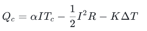
Parameter Definitions and Units:
- Qc: Cold-end net refrigeration capacity (W), actual available cooling capacity of equipment
- α: Seebeck coefficient (V/K), inherent TEC chip parameter determined by semiconductor materials
- I: TEC operating input current (A)
- Tc: Cold-end absolute temperature (K), Tc = Celsius temperature + 273.15
- R: Internal resistance of TEC thermopile (Ω), inherent chip parameter
- K: Overall TEC thermal conductivity (W/K), characterizing natural heat conduction loss between cold and hot ends
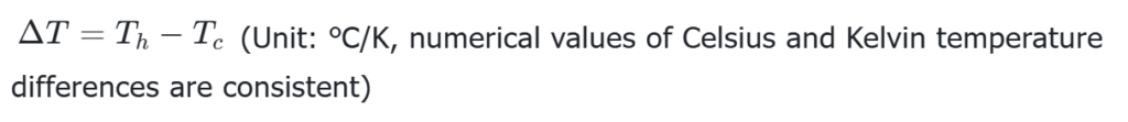
- ΔT: TEC cold-hot end temperature difference (K/℃), ΔT = Th-Tc, Th = hot-end temperature
Core Formula Logic: The actual effective refrigeration capacity equals the theoretical heat absorption generated by the Peltier effect minus Joule heat loss from current heating and heat leakage caused by thermal conduction across cold and hot ends.
3.2 Hot-End Total Heat Dissipation Formula
According to the law of energy conservation, the heat to be dissipated by the TEC hot end includes heat transferred from the cold end and power consumption from self-operation, serving as the core basis for radiator selection:
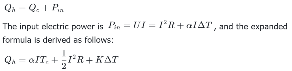
Key Engineering Conclusion: The heat dissipation pressure of the hot end is always higher than the refrigeration capacity of the cold end. Most TEC cooling failures are caused by insufficient radiator selection and hot-end heat accumulation.
3.3 TEC Temperature Difference Core Calculation Formulas
3.3.1 Real-Time Operating Temperature Difference Formula
3.3.2 No-Load Maximum Temperature Difference Formula
Under no external thermal load and ideal heat dissipation conditions, the maximum cold-hot end temperature difference achievable by TEC represents the inherent performance limit of the chip:
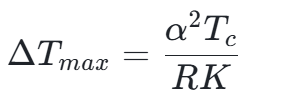
Key Conclusion: The maximum TEC temperature difference is positively correlated with the material thermoelectric figure of merit and cold-end temperature, and negatively correlated with internal resistance and thermal conductivity. The lower the temperature, the smaller the limit temperature difference, resulting in continuous attenuation of TEC refrigeration efficiency under low-temperature working conditions.
3.4 Refrigeration Efficiency COP Formula (Coefficient of Performance)
COP is the core index for evaluating TEC refrigeration economy, with a higher value indicating better energy efficiency:
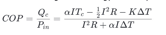
General Engineering Rule: The TEC refrigeration COP is generally less than 1 under normal room-temperature working conditions. Larger temperature differences and higher operating currents lead to lower COP and more severe energy waste.
4. Complete TEC System Heat Transfer Linkage and Loss Analysis
TEC refrigeration is not limited to a single chip operation. The complete heat transfer forms a four-stage series thermal resistance linkage. The total system temperature difference is determined by all thermal resistances, which is the key to engineering temperature difference calculation and the most easily overlooked point for beginners.
4.1 Complete Heat Transfer Path
Controlled Heat Source → TEC Cold End (Heat Absorption) → Semiconductor Thermopile (Heat Transfer) → TEC Hot End (Heat Release) → Radiator (Convection & Radiation Heat Dissipation) → Ambient Air
4.2 Total System Thermal Resistance and Temperature Difference Calculation
Thermal resistance is defined as the temperature rise generated by unit power heat passing through the medium, with the unit of ℃/W. Series thermal resistances follow the superposition principle.
Total system thermal resistance:
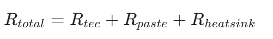
Parameter Definition: Rtec = TEC chip body thermal resistance; Rpaste = thermal grease/thermal pad contact thermal resistance; Rheatsink = heat sink thermal resistance (0.1~1.0℃/W for conventional air-cooled radiators).
Total system temperature difference calculation formula:

Practical Engineering Conclusion: To reduce the overall temperature difference and improve cooling performance, priority should be given to lowering radiator thermal resistance and interface thermal resistance. Such optimization delivers far better results than blindly increasing TEC operating current. Excessively high current only intensifies Joule heat loss and reduces net refrigeration capacity.
4.3 Three Core Heat Loss Mechanisms
- Joule Heat Loss: Irreversible heat generation caused by current passing through semiconductor internal resistance. Higher current leads to exponentially increased loss, which is the main cause of efficiency collapse under high-current conditions.
- Cross-End Thermal Conduction Loss: When a temperature difference exists between cold and hot ends, heat spontaneously transfers from the hot end to the cold end through the semiconductor medium. A larger temperature difference causes more severe heat leakage, directly offsetting the refrigeration effect.
- Reverse Electromotive Force Loss: The Seebeck reverse voltage generated by the cold-hot end temperature difference offsets the input driving voltage, reduces effective operating power and limits the maximum cooling capacity.
5. Simplified Engineering Calculation Case (Directly Applicable)
Standardized simplified calculations are conducted based on the commonly used TEC12706 cooler under room-temperature conditions for beginner-friendly quick application.
5.1 Known Conditions
Ambient temperature = 25℃ (298.15K), operating current I = 4A, internal resistance R = 2.2Ω, Seebeck coefficient α = 0.052V/K, thermal conductivity K = 0.18W/K, steady-state cold-hot end temperature difference ΔT = 40℃
5.2 Step-by-Step Calculation
1. Input Electric Power: Pin=I²R=4²×2.2=35.2W
2. Cold-End Theoretical Heat Absorption: αITc=0.052×4×298.15≈62.02W
3. Joule Heat Loss: 0.5I²R=0.5×35.2=17.6W
4. Cross-End Thermal Conduction Loss: KΔT=0.18×40=7.2W
5. Net Refrigeration Capacity: Qc=62.02-17.6-7.2=37.22W
6. Hot-End Heat Dissipation Capacity: Qh=Qc+Pin=37.22+35.2=72.42W
7. Refrigeration COP=37.22÷35.2≈1.06 (Optimal conventional working condition)
5.3 Core Case Conclusion
Under this working condition, the effective TEC refrigeration capacity is only about 60% of the theoretical maximum value, with nearly 40% of power consumed by internal losses. Meanwhile, the radiator needs to bear a heat dissipation load of 72.42W. Excessively high radiator thermal resistance will raise the hot-end temperature, further expand the temperature difference and continuously reduce the refrigeration capacity.
6. Common TEC Refrigeration Misunderstandings and Optimization Solutions
6.1 Common Cognitive Misunderstandings
- Misunderstanding 1: Higher current brings better cooling performance. In fact, when exceeding the optimal current, Joule heat loss increases exponentially, resulting in a rapid drop in net refrigeration capacity and even temperature rise instead of cooling.
- Misunderstanding 2: Focusing only on TEC parameters while ignoring heat dissipation matching. The upper limit of TEC refrigeration is determined by hot-end heat dissipation capability; insufficient heat dissipation directly locks the maximum temperature difference.
- Misunderstanding 3: Ignoring interface thermal resistance. The absence of thermal grease or excessively thick thermal pads will significantly increase the total system thermal resistance, causing virtual high temperature and refrigeration failure.
6.2 Core System Optimization Solutions
- Optimal Current Matching: Each TEC chip has a exclusive optimal operating current (not the maximum current). Operating at the optimal current balances refrigeration capacity and COP.
- Hot-End Priority Heat Dissipation: The selected radiator power should be 1.2~1.5 times the total TEC hot-end heat dissipation capacity to reserve sufficient heat dissipation margin.
- Reduction of Interface Thermal Resistance: Apply thermal grease evenly with a thickness of 0.1~0.2mm to avoid cavities and bubbles, minimizing contact thermal resistance.
- Controlled Operating Temperature Difference: Based on formula characteristics, TEC achieves high efficiency under small temperature difference conditions. Multi-stage TEC series refrigeration is recommended for large temperature difference scenarios.
7. Conclusion
TEC refrigeration is essentially a reverse heat transfer process driven by electric energy, and all its operating characteristics are determined by the Seebeck effect, Peltier effect and thermodynamic losses. The core calculation logic is summarized as: Net Refrigeration Capacity = Theoretical Peltier Heat Absorption – Joule Heat Loss – Cross-End Heat Leakage; the system temperature difference is determined by the series connection of chip thermal resistance, interface thermal resistance and radiator thermal resistance. In engineering applications, blind selection, parameter adjustment and heat dissipation design without formula support are the fundamental causes of poor TEC refrigeration performance and high failure rates.
The complete set of standardized formulas, heat transfer links, temperature difference calculation methods and engineering cases sorted out in this paper can cover the design and calculation requirements of most civil and industrial TEC temperature control scenarios. Accurate formula application and reasonable matching of thermal resistance and current parameters can maximize TEC refrigeration efficiency, reduce energy consumption, avoid equipment failures and achieve high-precision and stable temperature control. As a professional thermal management supplier, ZICOTEC has in-depth expertise in TEC thermoelectric refrigeration and precision thermal management. Based on complete thermodynamic calculation standards, ZICOTEC provides efficient and high-stability customized thermal management solutions for precision equipment, industrial temperature control and smart hardware products. We deliver full-process services including chip selection, thermal resistance matching and heat dissipation system optimization, solving core problems such as low efficiency, insufficient temperature difference and unstable operation of conventional TEC systems, and helping products achieve extreme temperature control performance and long-term reliability.
References
[1] High-Precision Temperature Control Algorithm Based on Thermoelectric Refrigeration Equivalent Circuit Model. Acta Physica Sinica, 2025.
[2] Principle and Engineering Application Optimization of Thermoelectric Refrigeration Technology. Industry White Paper, 2026.
[3] Thermal Resistance Matching and Temperature Difference Calculation Standard for Semiconductor Refrigeration Chips. Electronic Engineering Technology, 2025.
www.zicotec.com